
Learning Targets
- Interpret the form and mounting features of an aerospace-style bracket.
- Create coordinated isometric and orthographic sketches of the same part.
- Add the critical dimensions needed to define the bracket.

Focus question: How can sketches communicate the shape, features, and size of a part before it is modeled or built?
Use this page with the lesson presentation and your engineering notebook.
The drawing package communicates the bracket’s form, mounting features, and required sizes consistently.
Think first, then be ready to share a short response that connects the question to engineering communication.
The engineer needs a clear overall form, coordinated views, mounting-feature locations, and critical sizes. The drawings must agree with one another.
A bracket supports, connects, or aligns other components.
An isometric sketch communicates overall form while orthographic views show precise feature placement.
Critical dimensions define the bracket envelope and mounting features.
Use the isometric bracket sketch as your reference. Imagine looking straight at the face with the semicircular cutout, then select the front view that matches the same geometry.
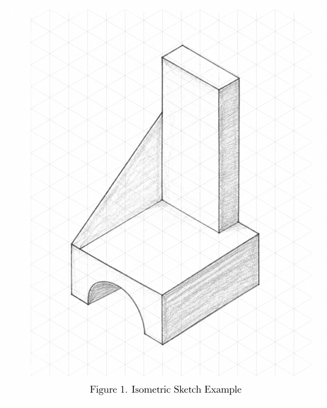
Front-view note: In this activity, the front view is the face that shows the semicircular cutout. Use that face to orient the sketch before you choose.
Develop a compact technical sketch package for a provided or assigned aerospace-style bracket.
Quality check: The isometric sketch, orthographic views, and dimensions must all describe the same part.
Submit one coordinated drawing sheet and one short design-intent note.
Submission standard: Use consistent feature names and geometry throughout the entire sheet.
Use the lesson slides for guided practice, interactive checks, and the exit ticket.
Return to the IED course hub for units, resources, certifications, and current course information.